PROJECT INFORMATION
Submitted by:
Jacob Dunn
Firm Name:
ZGF
Other contributors or acknowledgements (optional)
Jason Essel – ZGF Project Architect
Project Name:
California Shading Scrim Study
ASHRAE Climate Zone:
3C
Building/Space Type:
Education
Who performed the simulation analysis? (select all that apply)
Architect – Internal Sustainability Personnel
What tools were used for the simulation analysis? (select all that apply)
Grasshopper Honeybee
What tools did you use to create the graphic?
Design Explorer / Excel
What phase of the project was analysis conducted? (select all that apply)
Design Development
PROCESS
List the investigations questions that drove your analysis process.
Can we increase the openness of our shading screen and stay under radiant cooling capacity targets? What combinations of other shading screen elements are needed to stay under the target?
How was simulation integrated into the overall design process?
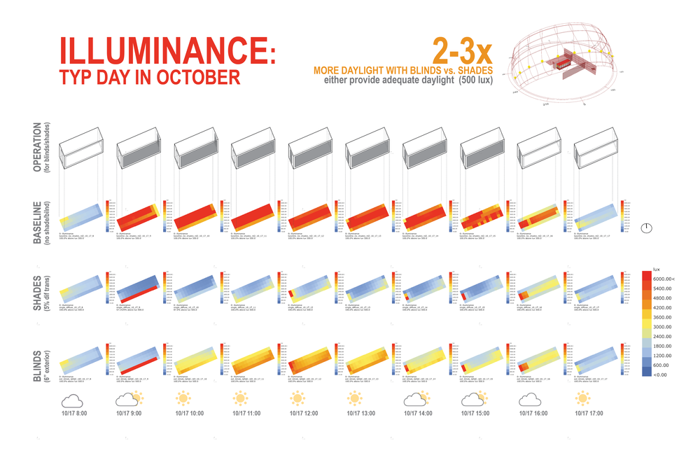
This study was conducted on the project during early design development after the mechanical engineer warned the design team that increasing the window to wall area ratio of the façade to 100% would increase the cooling load beyond the proposed radiant panel system’s capacity. When a perforated shading screen was proposed, the mechanical engineer stipulated that a 40% openness factor would be sufficient to prevent the costly impact increasing the size of the DOAS system’s capacity and ductwork to handle the increased load.
A 40% open screen was deemed to be too occluded by the design team from an experiential standpoint, so they worked with an internal sustainability team member to conduct a more detailed study of the screen and its components. The following additional variables beyond screen openness were identified:
• Shading structure fin depth and distance from the facade
• Shading structure fin rotation
• Catwalk presence and depth
• Frit coverage
• Window to wall area ratio
Ranges of values for each variable were defined and 3 rounds of analysis and design iterations were tested. The first round included analyzing how much over the target load capacity openness factors greater than 40% produced. This effort produced the amount of load that various other measures had to mitigate. In the next two cycles of iterations the design team would draw up various screen designs and the energy modeler would test them across the full range of possibilities.


How did you set up the simulation analysis and workflow?
The first step in the process involved reaching out to the mechanical engineer to get the load breakdowns for a selected worst-case scenario west-facing zone. The solar load was extracted from the load data sheets and used to validate a separate model created using a Grasshopper Honeybee workflow. Once the new model produced a similar solar load, the team could be confident moving forward to test different solutions using that model’s outputs.
Given only a single zone was isolated for analysis, the modeler re-created the geometry from scratch in Rhino. Additionally, only solar load outputs were needed so the energy model could be defined using minimal Honeybee components and relying on defaults for things like HVAC systems, envelope components (other than the glass), and internal gain inputs/schedules. To simulate the openness factor of the perforated screen, the EnergyPlus window shade generation Honeybee component was used, which allows detailed blind slat modeling and control. Various slat depths and spacing were defined as a proxy for openness factor, while the other geometric components of the screen (structural fins, catwalks, etc.), were modeled directly in Rhino and parametrically controlled using Grasshopper. The solar load from each run was extracted from the .eio output using Honeybee components, so each simulation produced a single output used to compare the effectiveness of each iteration.
How did you visualize the results to the design team? What was successful about the graphics that you used to communicate the data?
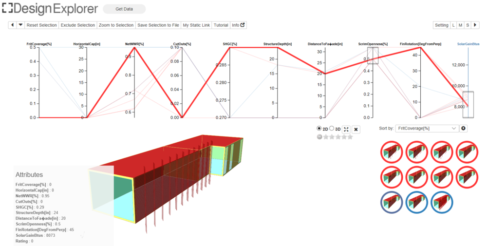
Originally, the modeler used a basic bar chart/table in Excel to report the cooling loads of each iteration during pinups about the screen with the design team. The target load was identified as a line across the charts and a table below the bars identified the inputs for each run. The widths of the cells lined up with the bar widths, while the rows represented each type of input and its range value. While this method clearly showed which iterations met the criteria, it was difficult to keep track of what combination of inputs each run included. Therefore, a completely different method was used to communicate with the design team at the end of this whole process.
The data was massaged into a .csv file and uploaded in a format that Design Explorer 2.0, a free online data viewer, required to produce an interactive parallel coordinate diagram. In this type of graphic, each column represents either an input or output and it’s constituent range of values. The user can then drag regions around each column to filter simulation cases according to different input combinations or output values. One added benefit of the Design Explorer 2.0 interface is that images can be associated with various simulation cases, so a visual representation is shown alongside the data. This feature is critical in both testing the concepts aesthetically and keeping track of input combinations, which are shown as a line on the coordinate diagram and listed once a case is clicked on.
To view the interactive parallel coordinate diagram, click here.
Most importantly, what did you learn from the investigation? How did simulation and its outputs influence the design of the project?
Visualizing the data in an interactive parallel coordinate diagram facilitated a much more interactive and engaging way for the designers to navigate the parameter space of the study. It was very easy for them to filter the solar load values for cases below the roughly 9,000 Btu load target, and to then filter the remaining options by desirable inputs and design considerations. Nothing new or novel was discovered as part of this investigation, rather, the effort produced a range of about 8 input combinations that met the design criteria. This gave the designers ample flexibility in designing the screen to meet both aesthetic and performance considerations. The results showed that to achieve the desired 60% open perforated screen, the window to wall area ratio had to be reduced by about 25%. Alternatively to the keep the fully glazed façade, either 50% frit coverage was needed, or rotated structural fins were necessary, both of which weren’t desirable from either an aesthetic or view preservation standpoint. In the end, the design team chose a spiral wire screen (an openness factor of 65%) and reduced the window to wall area ratio while adding a horizontal catwalk for maintenance and shading purposes.